Basic HTML Version


www.geotechnicalnews.com
Geotechnical News • March 2013
41
extension cracks along the tunnel
lining. In the transverse section of
a circular tunnel, for instance, the
ground shaking induces ovalization
of the lining ([4]). Hence, depending
on the stress level of the lining under
‘static’ conditions, cracks may open
where tensile stress increments arise
during shaking (Fig.1).
Although it is quite difficult to mea-
sure such increments of internal forces
during real earthquakes, centrifuge
modeling allowed an experimental
assessment of these quantities during
‘artificial seismic events’; the results
may be used for benchmarking simpli-
fied to complex prediction methods.
Four centrifuge tests were carried out
in 2007 at the University of Cam-
bridge (UK) on tunnel models in
sand ([5], [6]), for the assessment of
different analytical methods developed
in the framework of a research project
(www.reluis.it ) funded by the Italian
Civil Protection Department. After the
end of the research project, the experi-
mental data have been made available
online to the scientific community
to be used for benchmarking simpli-
fied to complex dynamic numerical
methods. In 2011, such a predictive
exercise, called RRTT (
Round Robin
Tunnel Test
) was officially launched
at the TC28 conference ‘Underground
constructions in soft ground’ in Rome
([7]).
All the models were made using dry
Leighton Buzzard sand (grade E)
reconstituted at two different relative
densities Dr (about 50% and 80%). A
detailed characterization of the sand
used in tests was purposely performed
in laboratory by means of triaxial
and resonant column - torsional shear
(RCTS) tests ([8]). The RCTS appa-
ratus was an upgrading of a Stokoe-
type fixed-free model ([9]), originally
developed at the University of Napoli
Federico II ([10]).
The tunnel lining was modelled using
an alloy tube having an external
diameter D=75 mm and a thickness t
=0.5 mm. At N=80g, the model would
correspond to a 6 m diameter proto-
type tunnel with a shotcrete lining of
about 6 cm.
Miniature piezoelectric accelerom-
eters were used to measure horizontal
and vertical acceleration in the soil
and on the model container during
earthquakes. The device has a reso-
nant frequency of about 50 kHz and
maximum error of 5%; the transducer
weight is about 5 grams.
The tube has been instrumented in
order to measure bending moments
(BM) and hoop forces (HS) at 4 loca-
tions along 2 transverse sections (Fig.
2).
The main instrumented section was
located at the mid-span of the tube and
a second section 50 mm aside. The
strain measurements on the tube were
purposely performed in two sections,
in order to check that no boundary
effects occurred and the plane strain
conditions were ensured. In total 16
Wheatstone bridges (4 locations x 2
sections x 2 force measurements) were
glued to the tube and wired.
The vertical displacement of the
surface during centrifuge tests was
measured by linear variable differen-
tial transformers (LVDTs) placed in
two gantries above the model.
Benchmark testing programme
and experimental data
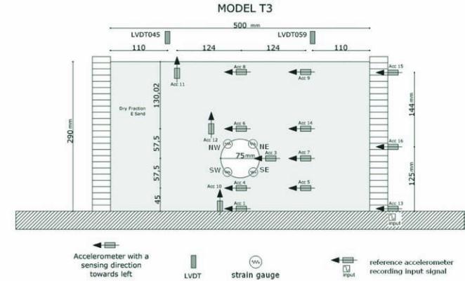
The tests selected for the benchmark,
T3 and T4, are two models of deep
tunnel in dense and loose sand, respec-
tively; the layout of the first of them
is drawn in Fig. 3. The model was
prepared by pluviation of about 50 kg
of sand in the container, obtaining the
Table 1. Earthquakes fired in test T3 - T4.
Earth-
quake #
N Frequency (Hz)
Duration(s)
Nominal PGA (g)
model
[proto-
type]
Model [proto-
type]
model
[proto-
type]
1
80 30 [0.375]
0.4
[32]
4
[0.5]
2
80 40
[0.5]
0.4
[32]
8
[0.10]
3
80 50 [0.625]
0.4
[32]
9.6
[0.12]
4
80 60
[0.75]
0.4
[32]
12
[0.15]
5
40 50
[1.25]
0.4
[16]
6
[0.15]
Figure 3. Model T3: layout of the instrumentation.