48
Geotechnical News • June 2016
GROUNDWATER
interface. During the autumn, the
lagoons were filled with cold water
and the temperature of the pipes
decreased to 5-10ºC: the 25-30ºC
change made the pipe diameter
decreased by 1-2 mm for pipes having
a diameter in the 30-60 cm range.
Unfortunately, the clay used for the
liner had no swelling capacity: it was
unable to follow the pipe thermal con-
traction. As a result, there was a small
annular space around each pipe, and
some arching effect in the clay. The
pore space existed when the lagoons
were filled (cold water in autumn)
and during the full-scale leakage tests.
Thus, a preferential leakage started in
the annular space. This leakage eroded
the clay and enlarged the initially
small space, up to 5–8 cm, during
the time the water level fell from its
maximum elevation down to the pipe
elevation, where the leak around the
pipes went dry.
This clay liner project provided a les-
son for subsequent projects in Quebec.
The design of seals around pipes was
modified. The next seals were made
using a rich soil-bentonite mixture,
30- to 50-cm thick. When the dry mass
of bentonite is 16-20% of the total dry
mass, the mixture can follow the pipe
thermal contraction and dilation with-
out losing the hydraulic seal. Such a
solution appears
in a photograph
for a much larger
project with large
pipes (see Fig.
8 in Chapuis
2002). In his
files, the author
has over twenty,
mostly unpub-
lished, cases of
failure for soil-
bentonite liners
and compacted
clay liners, but
this case (one of
earliest cases of
liner construction
and liner failure
in the author’s
files) was the
first and last one with a sealing defect
around plastic pipes.
Reconstruction in the
mid-1980s
The upper parts of the liners were
rebuilt with the same clay. The field
geotechnical control was continuous
instead of part-time during initial con-
struction. For reconstruction, it was
suggested that the pipes be sealed with
a soil-bentonite mixture. This sugges-
tion was followed by the consulting
engineer and used by the contractor.
Immediately after the repairs, the
two lagoons were filled, up to their
top levels. All valves on the pipes
were closed, and the leakage rate of
each lagoon was measured. The two
liners passed the new tests and were
accepted. Since the 1980s, they have
performed well, as indicated by their
low leakage rates, which can be moni-
tored in the filtering-drainage system
below the liners.
Availability of new predictive
and control tools
In the 1980s, predictive and control
tools had serious limitations. This was
an incentive to develop closed-form
solutions for analyzing full-scale leak-
age tests and detecting the position
and stability of different types of
hydraulic defects. Closed-form solu-
tions were developed and then verified
with a few poorly performing liners.
They provided correct diagnoses, and
all liners were successfully repaired.
Afterward, closed-form solutions were
published (Chapuis 1990a, b). These
were also used to predict the infill-
ing rate of shallow lagoons which are
filled slowly once a year, then emp-
tied, and for which meteorological
conditions, which can bring 50 cm of
rain water or snow water, may be criti-
cal (Chapuis 1991a, b). Later, equa-
tions were developed to predict the
K
value of compacted clay (Chapuis
2002, 2012; Chapuis et al. 2006):
these equations use field compaction
data to predict a
K
value at each place
a compaction control was carried out.
Recently, a statistical method was also
developed (Chapuis 2013) to predict
the full-scale leakage of a liner, using
the small-scale
K
values predicted
with compaction control data.
The 1990 closed-form solutions were
proven correct in a few published
cases (Chapuis et al. 1992; Chapuis
2002), but the author has only pub-
lished a few of the many failure cases
for which he was an expert. The
closed-form solutions for the local val-
ues of
K
, and the resulting large-scale
value of
K
, were verified recently
(Chapuis 2013) for a case of frost
damaged liners. More case studies are
needed for full proof of correctness.
The compaction data of the two clay
liners of this paper, built and success-
fully repaired in the 1980s, provide an
opportunity to test the new predictive
methods, because they permit direct
comparison between predicted and
measured total leakages. This detailed
comparison will be presented in
another paper.
Discussion and conclusion
Two compacted clay liners were
constructed, tested for full leakage,
poorly performed, but were success-
fully repaired in the 1980s. Both liners
failed the first full scale leakage tests.
Each liner had a total leakage rate
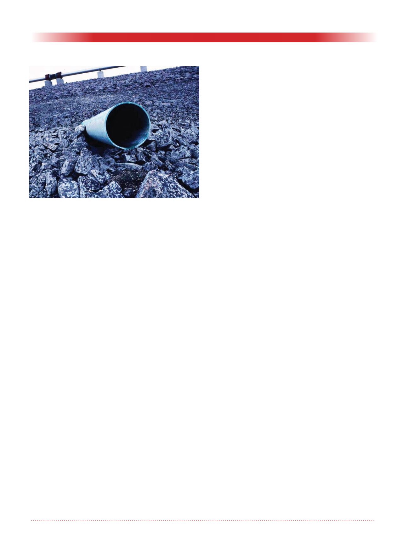
Figure 4. Photograph of the poor contact between a pipe
and the clay liner (photo by author). A large opening
appears as a black crescent below the pipe.


