Basic HTML Version


www.geotechnicalnews.com
Geotechnical News • December 2013
31
GEOTECHNICAL INSTRUMENTATION NEWS
0 80 160
N
SPT
(per 0.3 m)
0 25 50
Tip Resistance
q
c
(MPa)
0 5 10
Friction Ratio
F
R
(%)
0 150 300
N
RTP
(per 0.3 m)
OCT 2010
Installation 1
Installation 2
Installation 3
0 100 200
Bounce
Chamber
Pressure (kPa)
Soil Profile
16
12
8
4
0
Depth (m)
Sand &
Gravel Fill
Dense
Sand
Soft Clay
Dense
Sand
Clayey
Silt
Silty Sand
Figure 5. Site profile as well as resistance measurements from SPT, CPT
and RTP systems.
with standard 152 cm (5 ft) and 305
cm (10 ft) long Becker pipes, enabling
positioning of the instrumented
sections in the drill string at target
final elevations required by project-
specific soil stratigraphy. Installation
is achieved using the conventional
Becker drilling system that is equipped
with an International Construction
Equipment (ICE) Model 180 double-
acting diesel hammer. Down-hole data
acquisition units (computer modules
manufactured by GeoDaq, Inc.) in
each RTP section provides signal
conditioning (sensor excitation, gain,
and filtering), digitizes and buffers the
signals, and transmits the data serially
(i.e. through additional computer mod-
ules in line) to the control unit above
ground (labeled GCM in Figure 1).
The digital transmission results in only
a single 4-wire cable running along the
RTP connecting all instrumented mod-
ules to the above ground computer.
The above-ground computer controls
which modules and sensors are con-
nected and should be recorded, as well
as the sampling rate and duration. A
separate above-ground data acquisi-
tion system (based on National Instru-
ments hardware; labeled NI-DAQ in
Figure 1) collects data from displace-
ment gages (string potentiometers) to
measure vertical displacement of the
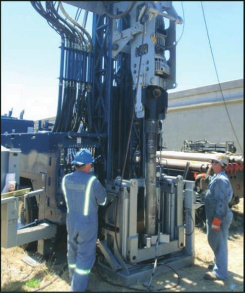
Figure 3. RTP driving.
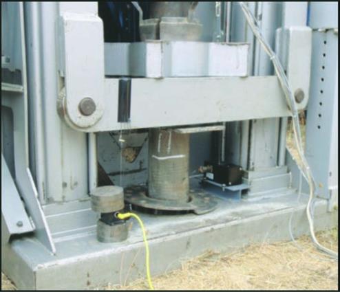
Figure 4. Load testing.