Geotechnical News • March 2016
43
THE GROUT LINE
• Analysis and reporting of grouting
results using SPHINX and SCAN
3-D
• Drilling of control holes, water
testing
• Preparation of 2D and 3D plots,
and tabulated analysis, using
SPHINX and SCAN 3-D
• Review of injection & water test
data
• Preparation of Black and Veatch
compliance documentation
Design and 3-D modelling
Due to the complex geometry of the
cut off, particularly around the culvert,
and the degree of uncertainty regard-
ing the profiles of the culvert planes
and rock head, it was considered
essential to establish a 3-D model to:
a. design the location of the grout
holes to ensure minimum spacing
b. define the zones of treatment for
the preparation of the electronic
grouting instructions
c. verify the continuity of the key cut-
off elements
A full 3-D model was prepared in the
CASTAUR-CAD geometry design
software, which was updated as the
works progressed on the information
from the driller’s logs, and the results
of borehole surveys using a Maxibor
instrument.
Grout curtain criteria
Maximum and average Lugeon values
were specified for the hydraulic con-
ductivity of the rock mass.
The specification called for a high
degree of control of the grouting
process, and the geometry of the grout
curtain, and required that the con-
tractor demonstrate continuity of the
cut-off. These issues were addressed
by employing an integrated system of
computer controlled grouting equip-
ment, and its dedicated IT suite of
software for the 3-D design, control,
management, and interpretation of
grouting operations. The system pro-
duces daily production reports in tabu-
lated and graphical analysis, and plots
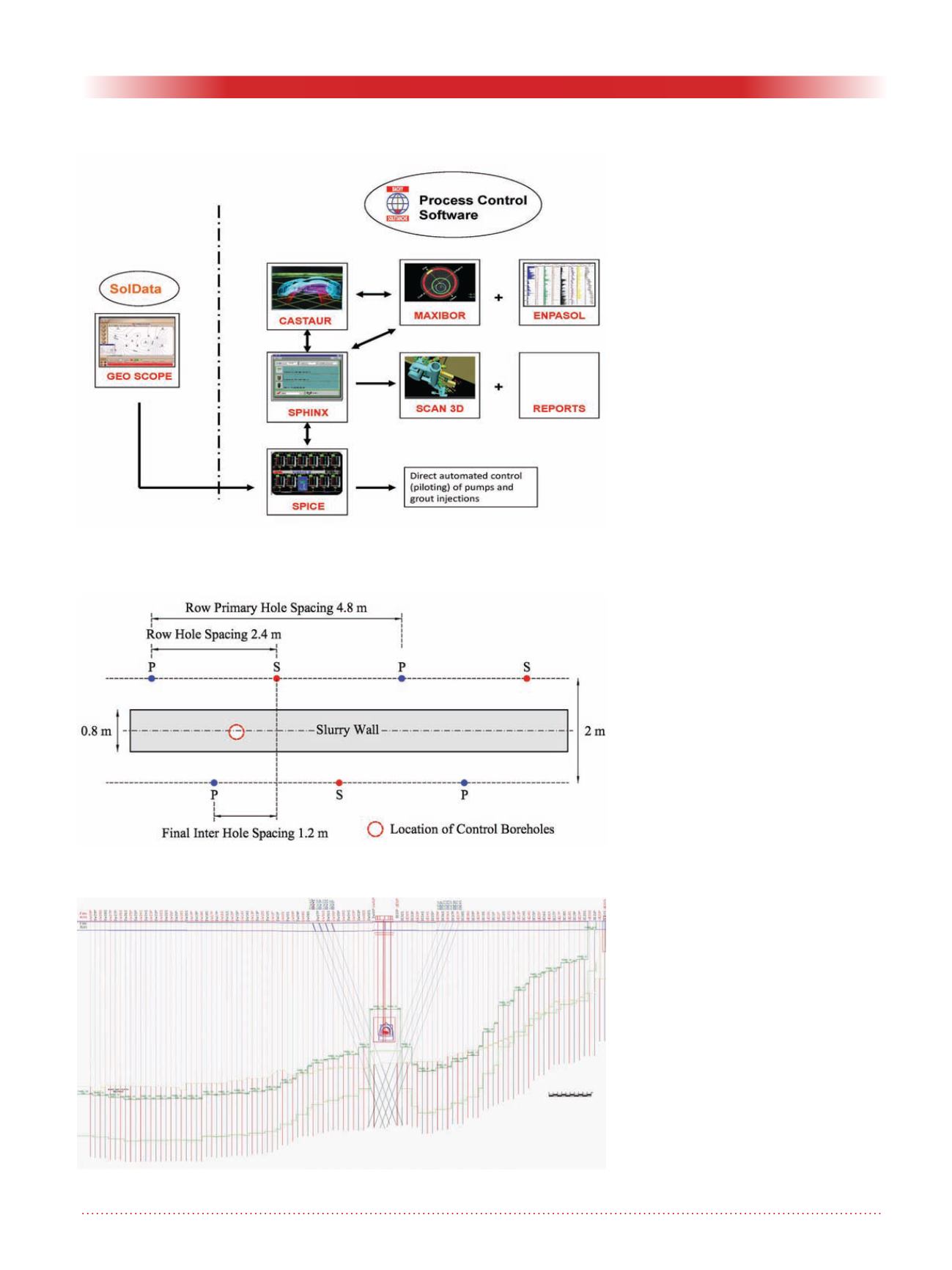
Figure 3. Inter-relationship between key components of the control software.
Figure 4. Grout hole / slurry wall geometry – plan.
Figure 5. Dam surface drilling geometry.


