Geotechnical News • March 2016
47
THE GROUT LINE
to drill down to the toe level of the
diaphragm wall to fill any major voids
or areas of fault breccia in advance
of diaphragm wall excavation, and
thereby avoid slurry loss during con-
struction.
Stage 2 grout curtain
The twin-row, 11 m deep, grout
curtain drilling and grouting was
executed via reservation pipes cast
into the diaphragm wall. Because of
the risk of faulting and borehole col-
lapse, grouting was carried out in a
classical method of descending stages
(1 m, 5 m, 5 m) using the C3S mix.
The objective was to extend the seep-
age path below the diaphragm wall to
reduce hydraulic
pressures and
facilitate the base
plug excavation
and construction.
Stage 3 base
plug
After completion
of the diaphragm
wall construc-
tion, the 8 m
thick grout plug
was planned to
be executed in
3 stages (2 m,
3 m, 3 m), by
descending stage
grouting via reservation pipes installed
in advance to 82 m depth. The objec-
tive was to provide a water-tight plug
to ensure the shaft excavation could
be completed in the dry, and thereby
mobilise the weight of the plug, and
the weight of the chalk between exca-
vation level and the plug, to resist the
hydraulic uplift. The hole spacing was
to be maintained at 1.5 m to ensure
that any sub-vertical fissures were
identified and effectively treated.
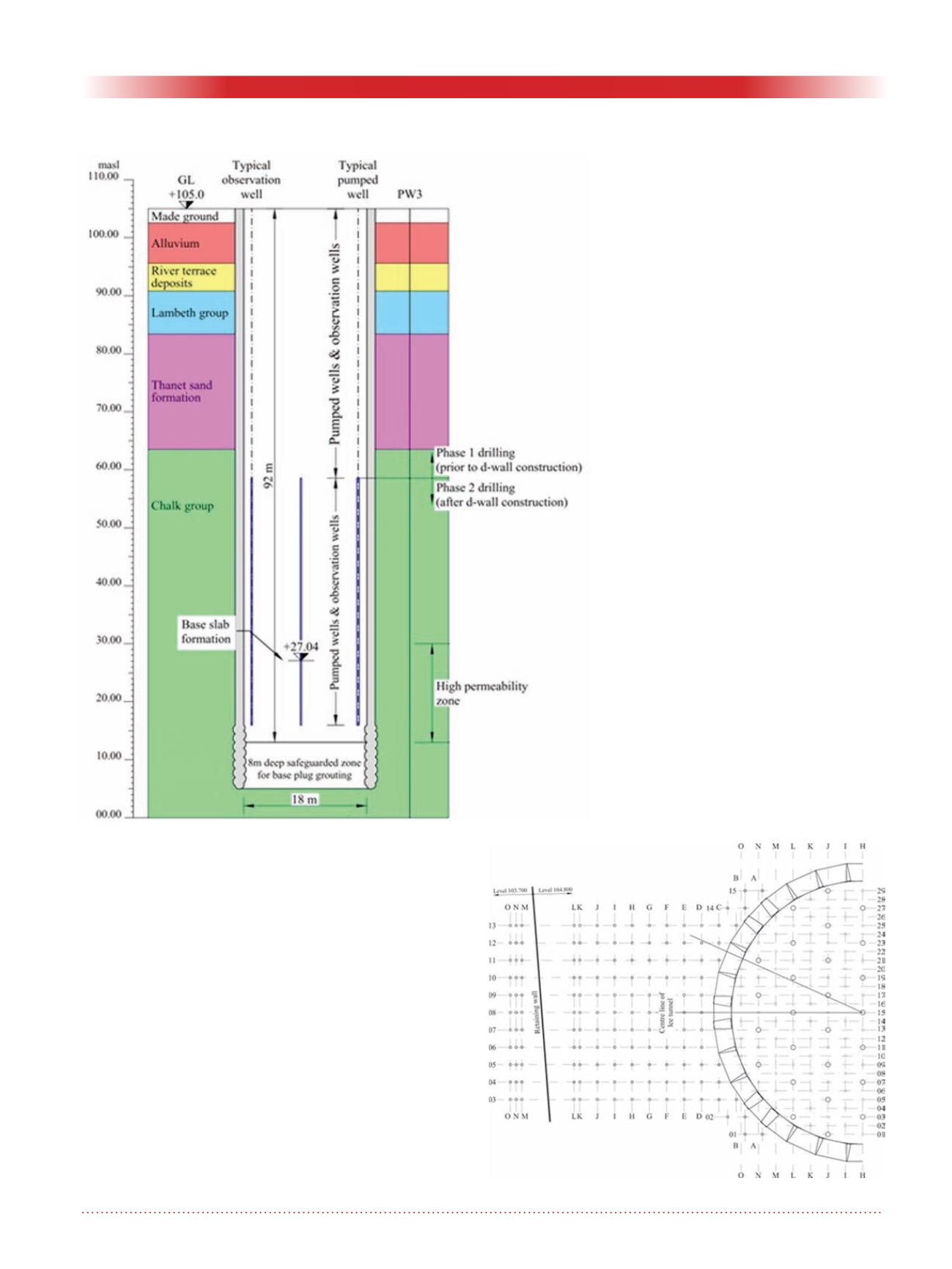
After the curtain grouting, a draw-
down pump test was carried out which
revealed that the total inflow would
be just 1.6 litre/ second - exception-
ally low for an opening of this size
and depth, and well below the target
inflow assuming the plug was in place.
On this basis it was agreed to delete
the base plug grouting and proceed
directly to the break-in and break-out
grouting.
Stage 4 TBM break-ins /
break-outs
The break-ins and break-outs were
treated from the surface via reserva-
tion pipes to consolidate the fissured
and weathered chalk, and exclude
water from the break-in and launch
chambers. The treatment block was 16
m x 16 m in cross section, enlarged at
the contact to provide an additional 3
m of annular cover and contact grout-
ing.
Figure 13. TBM break-in.
Figure 12. Pumping tests in shaft.


