46
Geotechnical News • March 2016
THE GROUT LINE
Quality control of the works, including
supervision, management, and materi-
als testing, exceeded the requirements
of the specification in every respect,
and all performance
criteria were achieved. The dam
has been returned to service, fully
impounded to enhanced service level,
with no evidence of seepage. Piezo-
metric and weir analysis has verified
that the efficiency of the cut off has
been restored.
Case History 2 – LeeTunnel, England, 2013
Ground treatment was executed at
several locations for the tunnelling
works to facilitate the construction of
large and deep shafts and connecting
tunnels (90 m deep x 30 m diameter)
in fissured chalk where there was a
significant risk of sub-vertical fissures
and faults. On the basis of previous
experience of chalk grouting for the
Thames Barrier, Channel Tunnel, and
other projects, a figure of 5% of the
rock mass was used to characterise the
volume of groutable fissures gener-
ally, and 20% within any major faults
or crush zones. A single fault was
expected to be present within the main
overflow shaft excavation.
It was decided to use the GIN tech-
nique to reduce the risk of fissuring
the weak and weathered chalk. The
mix selected was C3S, a stable and
highly penetrating grout consisting of
OPC, de-flocculated bentonite slurry,
and fluidifier. This mix is well proven
over many years for both remedial
works and original grouting.
The depth of treatment for all of
the required areas was too great for
inclined drilling to address the risk of
vertical fissures, so the borehole grid
was reduced to a very conservative 1.5
m x 1.5 m spacing.
Stage 1 pre-treatment
Stage 1 comprised the pre-drilling,
along the centreline of the diaphragm
wall, using open-hole drilling tech-
niques with a cement-bentonite slurry
as flushing medium. The objective was
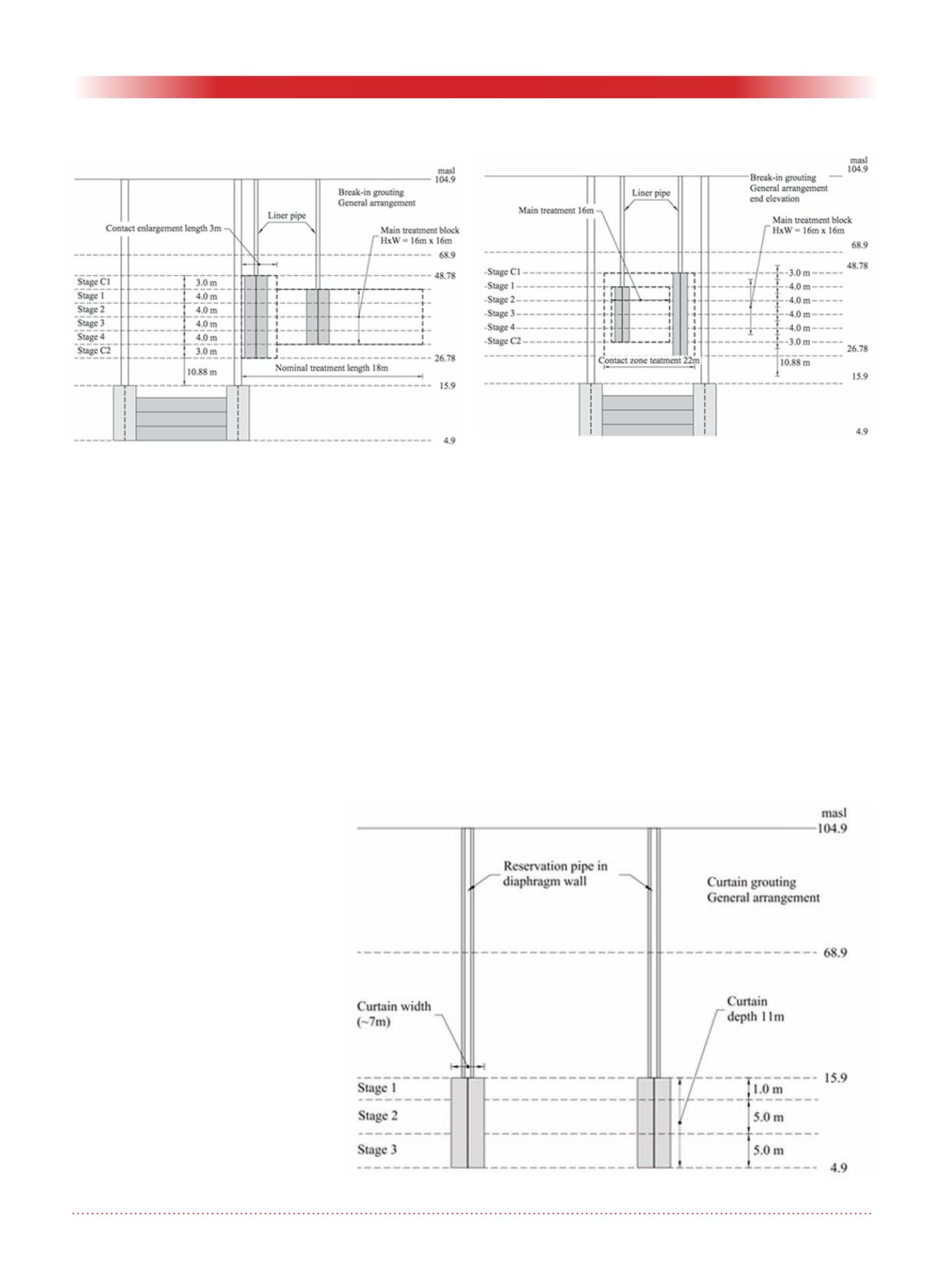
Figure 9. Break-in grouting - general arrangement.
Figure 11. Grout in grouting - General arrangement.
Figure 10. Break-in grouting - General arrangement. End
elevation.


